
 Manual
 Firmware
 Software
 Useful terms
 FAQ
FAQ Guarantee terms and conditions
3DGENCE SLICER
-
Warping
This is a negative phenomenon that occurs in FFF prints affecting mainly the materials with a high thermal shrinkage. It consists in tearing the most external print elements, most commonly the corners, from the printing bed. It is prevented by using a heated table and working chamber of the device.
-
Support
This is a support added by a model designer or a slicing software (3DGence Slicer) in order to form a supporting frame for the parts of the model suspended in the air. A correctly made support is not a part of a model and can be easily removed once the printing is completed. 3DGence Slicer automatically generates supports. The support generated by 3DGence Slicer consists of two parts – a loose laid material and the so-called dense support layers, directly supporting the model itself.
-
STL
Surface Tessellation Language – one of the basic formats of 3D files. It describes only the layout of triangle apexes that make up the solid and the orientation of normal for those triangles. It does not include any information on color, materials, textures or other graphical elements being part of other more extensive 3D file formats. Originally implemented by 3D Systems company for the use of stereographic printing.
-
Slicing
The process aimed at generating paths and instructions for the printer (machine code, G-code) from a 3D model. At the level of slicer we can choose such settings as layer thickness, print speed, filling density, thickness of solid walls or nozzle and printing bed temperature. In addition, it is also possible to select the use and the density of supports and one of the few ways of improving the print adhesion to the bed (e.g. raft or brim). The 3DGence printers use the 3DGence Slicer program with predefined settings from various materials and resolutions. The final effect of slicer operation results in obtaining a machine code representing a specific 3D model in the form of G-code (g-code, *.GCODE) that is subject to interpretation by the printer electronics.
-
Skirt
Additional material printed around the model at a distance of a few millimeters from it at the very beginning of the print. The Skirt does not make an integral part of a model. Its function is to initialize and stabilize the flow of plastics through the hotend. By observing the way the printer lays skirt on the table we can assess if the table is correctly leveled and if the print adheres to it.
-
Raft
One of the methods of enhancing print adhesion to the working table. The raft is the base (bed) with a thickness of a few alternately applied layers that is generated by the slicer under the model. The raft is larger than model outline, which increases print adhesion to the table and prevents from thermal shrinkage effects (plastic to plastic connection). Another advantage of the raft is its capacity to smooth minor uneven areas of the working table. The raft makes it also easier to print models without a flat surface that could make a base. Brim and the raft should not be used simultaneously.
-
PVA
Polyvinyl alcohol – a water soluble vinyl alcohol polymer. It is used to produce water-soluble filaments, perfectly suitable for printing support structures in dual-material printing. The model itself is printed with an insoluble plastic (the most commonly with PLA), which allows for its accurate cleaning in water bath. Using an ultrasound washer results in significant acceleration of the process.
-
PLA
Polylactide – a lactic acid polymer – produced in industrial quantities with use of eco-friendly methods. The main sources for initial materials include grains, e.g. cornflour or bacterial cultures. This is a basic material for FFF technology 3D printing. Low costs, no thermal shrinkage, good adhesion to the bed and multiple filler and color variants make the PLA the most versatile and most commonly used filament. During printing it gives off a weak, neutral odor, does not emit harmful substances and is fully biodegradable. It is more fragile and susceptible to mechanical damage than ABS, that’s why its use to manufacture the prototypes of mechanical devices is limited.
-
Overhang
This is a shape of the part of a model with special significance from the point of FFF printing. An overhang can be found where a model plane forms an overhang over the working table or other model part. The 3DGence Slicer software identifies those areas and analyzes the overhang angle in relation to the working table. If the angle exceeds the value of limit angle predefined in the software, the 3DGence Slicer program automatically generates support structures for such a surface.
-
OBJ
This is a popular format of 3D files. It may contain an additional MTL (Material Template Library) file irrelevant for FFF print, containing information on material libraries defined for the model. OBJ files apart from the geometry description, apex layout and normal orientations includes information on UV coordinates for textures. It is read by the 3DGence Slicer program.
What to do if any problem with the printer occurs?
Please read the instruction added to the printer before turning it on for the first time (Quick Start Quide).
- Report a problem with the device using:
– the form available on the website www.3dgence.com/support in Report problem category,
– contact form on the 3DGence CLOUD platform (cloud.3dgence.com). - Wait for the initial diagnosis and response from 3DGence support.
- When 3DGence support has confirmed that the device has to be sent to the service, send the device to the following address:
3DGence Sp. z o.o.
Graniczna 66
44-178 Przyszowice
Poland
phone: +48 32 438 98 64 - A precondition for accepting a defective Product by the service outlet is:
– registration of the Product on the www.3dgence.com/support website and attachment of the Product purchase evidence during registration;
– decision of 3DGence Technical Support Department with regard to the necessity of shipping the Product to service;
– filling in of the service report form received by e-mail from 3DGence and attaching the same to the shipment;
– sending information regarding the Product shipment to service at least one day in advance, to the address: support@3dgence.com. - Reporting a Product defect and its shipping to the service is equivalent to the acceptance of the rules comprised in the service report.
What software is intended for 3DGence INDUSTRY F42x?
Dedicated 3DGence Slicer 4.0 software has been prepared for the 3DGence INDUSTRY F420 printer. The software is designed to prepare machine codes (.3dg file) from files describing spatial geometry (.stl file). It also contains ready-made print settings for dedicated materials.
How to install the polymer pad?
NOTE: The protective gloves included in the set are required to perform the activities described.
When installing a pad, care must be taken not to damage the white gasket in the heated print bed.
The following procedure describes how to install the polymer pad in the 3DGence INDUSTRY F420 printer:
- Turn on the printer.
- In the printer menu, start the assembly printing surface assistant by selecting setting icon → maintenance → “assembly printing surface” button.
- The printer display will display a message requesting you to select the printing surface you want to mount on the printer. When installing the pad, select “foil” and follow the messages displayed on the printer screen.
- The print module and the Z axis column will be set in the correct position to allow the procedure to run smoothly.
- If the temperature in the working chamber is too high, the corresponding message will be displayed. Wait until the temperature is safe to continue.
- If the work chamber door is closed, an appropriate message will appear indicating that it must be opened.
- Tilt the two side locks (Fig. 1, grey) using the handles (Fig. 1, black).
- When a glass pane is installed in the printer, a message will appear that it must be removed.
- Remove any soiling or residual material from the vacuum plate, then wash the gasket with isopropyl alcohol and soft cloth. Any soiling can result in difficulties in keeping the pad on the bed.
- Place the pad on the vacuum table. Please note that the type of washer should be selected conforming with the type of material and the material profile selected.
- After accessing the next step on the display, the printer will check if the vacuum is maintained and the pad is properly sucked in place. If this is not the case, a message appears to press the pad with as large area as possible with your hand to the vacuum table.
- After the pad has been properly sucked, degrease the surface of the pad with isopropyl alcohol.
- After the procedure is complete, close the work chamber door to complete the procedure of mounting the pad.
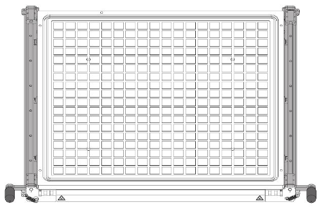
Fig. 1 Installation of the polymer pad – tilting the handles
How to install the glass printing surface?
NOTE: The protective gloves included in the set are required to perform the activities described.
When installing a glass plane, care must be taken not to damage the white gasket in the heated print bed.
The following procedure describes how to install the glass printing surface in the 3DGence INDUSTRY F420 printer:
- Turn on the printer.
- In the printer menu, start the assembly printing surface assistant by selecting setting icon → maintenance → “assembly printing surface” button.
- The printer display will display a message requesting you to select the printing surface you want to mount on the printer. When installing a glass pane, select “glass” and follow the messages displayed on the printer screen.
- The print module and the Z axis column will be set in the correct position to allow the procedure to run smoothly.
- If the temperature in the working chamber is too high, the corresponding message will be displayed. Wait until the temperature is safe to continue.
- If the work chamber door is closed, an appropriate message will appear indicating that it must be opened.
- Tilt the two side locks (Fig. 1, grey) using the handles (Fig. 1, black).
- Place the glass pane on the heatbed (Fig. 2, blue). A printer sensor will read if the glass pane has been placed.
- Using the handles (Fig. 3, black) close side locks (Fig. 3, grey) and make sure the glass heatbed is clean.
- Close the work chamber door to complete the procedure of mounting the glass printing surface.
NOTE: Before printing, check that the selected materials do not require the use of an appropriate adhesive agent. Recommendations for printing from individual materials are available at: www.3dgence.com/support

Fig. 1 Heatbed installation – tilting the handles
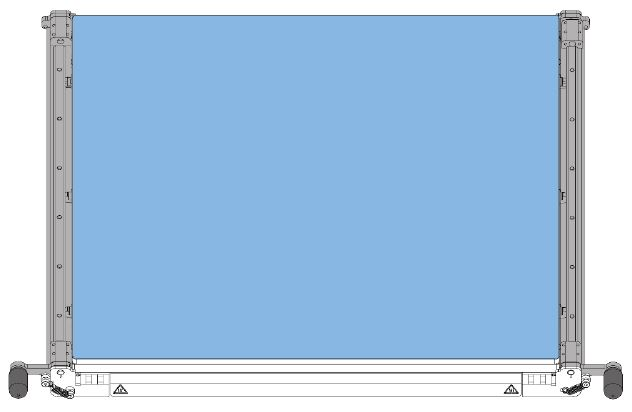
Fig. 2 Heatbed installation – glass placement
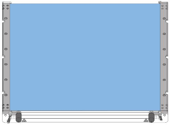
Fig. 3 Heatbed installation – closing the handles
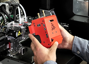
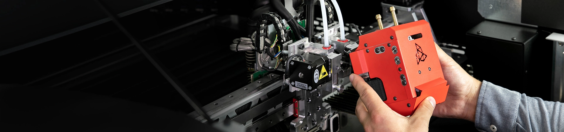
How to remove the printing module?
NOTE: The print module must be removed when the printer is switched off.
The protective gloves included in the set are required to perform the activities described.
Module removal procedure:
- Turn on the printer.
- Open the printer front door.
- Open the printer top cover.
- In the printer menu, start the module removal assistant by selecting the materials icon → model and support hotend icons → “remove module” button.
- If materials are loaded, the printer will unload them first. Follow the instructions displayed on the printer screen.
- The device then cools down to a safe temperature, the module trolley moves to the correct position and the printer switches off.
- Unlock the T0 extruder from the hotend sleeve by pressing the T0 extruder locking mechanism (Fig. 1, blue). The properly unlocked extruder will remain in a higher position (Fig. 2, grey).
- Unlock the T1 extruder from the hotend sleeve by pressing the T1 extruder locking mechanism (Fig. 1, blue). The properly unlocked extruder will remain in a higher position (Fig. 2, grey).
- Unscrew the knob above the module until you can remove the module slot from the mounting plate.
- Slide the dual hotend module out of the mounting socket. When pulling out the module, gently lift the extruders up, if necessary.
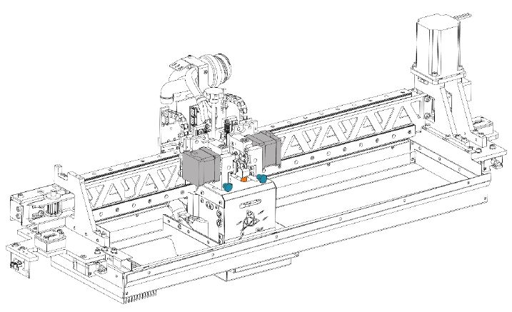
Fig.1 Removal module, step 1
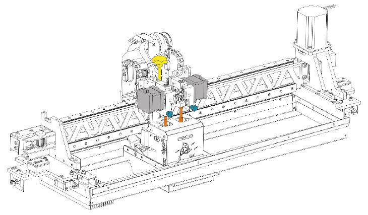
Fig. 2 Removal module, step 2
How to install the printing module?
NOTE: The print module must be mounted when the printer is switched off.
The protective gloves included in the set are required to perform the activities described.
Module installation procedure:
- Turn on the printer.
- Open the printer front door.
- Open the printer top cover.
- In the printer menu, start the module installation assistant by selecting the materials icon → model and support hotend icons → “install module” button.
- Turn off the printer.
- Prepare a new module and remove the black blanking plug marked “please remove”, which protects the module socket.
- If necessary, place the module trolley in a position where it makes it easy to access and mount the module.
- Fit the module plug (Fig. 1, blue) to the socket on the module trolley plate (Fig. 1, blue). Gently insert the plug into the socket (Fig. 2). Two positioning pins (Fig. 1, orange) and a ball pin (Fig. 1, yellow) will force the module to be installed in the correct position. Be careful not to scratch the front cover of the module during installation.
- Tighten the knob above the module (Fig. 3, yellow). The knob should be tightened as far as it will go to eliminate the play.
- Press and hold the T0 extruder locking mechanism (Fig. 3, blue), then lower the T0 extruder and release it (Fig. 3, grey). Check that the extruder is locked on the hotend sleeve (Fig. 3, orange) by pushing it up a little. The properly locked extruder will remain in a lower position (Fig.4, grey).
- Press and hold the T1 extruder locking mechanism (Fig. 3, blue), then lower the T1 extruder and release it (Fig. 3, grey). Check that the extruder is locked on the hotend sleeve (Fig. 3, orange) by pushing it up a little. The properly locked extruder will remain in a lower position (Fig. 4, grey).
- Close the top cover of the printer.
- Open the front door of the printer.
- Turn on the printer.
NOTE: Each time you install the print module, calibrate the offset between the hotends in the print module in the Z axis and then in the X axis, Y axis.
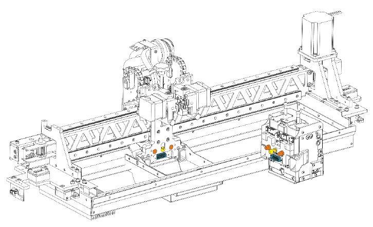
Fig. 1 Print module installation, step 1
Fig. 2 Print module installation, step 2

Fig. 3 Print module installation, step 3

Fig. 4 Print module installation, step 4
How to switch off the printer?
- Make sure the printer is not printing.
- Press the power button located on the left side of the front panel (Fig. 1, point 3).
- Confirm the on-screen message that you want to switch the printer off. When the message is not confirmed, the printer will return to the main menu and will not be switched off.
- After confirming the message, wait for the printer to cool down and reach a safe temperature. When a safe temperature is reached, the printer switches off automatically.

Fig. 1 3DGence INDUSTRY F420 printer – front view: 1. Light tower (optional) | 2. Display | 3. Power button 4. Working chamber door | 5. Accessories chamber door | 6. Stabilising feet | 7. Castor
NOTE: after you select the power button, do not disconnect the printer from the power supply before it cools down and switches off.
NOTE: the procedure described disables the power supply to the electronics only. To completely turn off the printer power, set the main switch and the overcurrent protection to OFF.
How to switch on the printer?
- Set the overcurrent protection located in the rear of the device to the upper ON position (Fig. 1, point 24).
- Set the main switch on the rear wall of the device to ON (Fig. 1, point 26).
- Press the power button located on the left side of the front panel (Fig. 2, point 3).
- The printer starts up and the touch screen is activated. During start-up, the printer will start preparing for operation, the startup screen will appear, followed by the printer main screen.
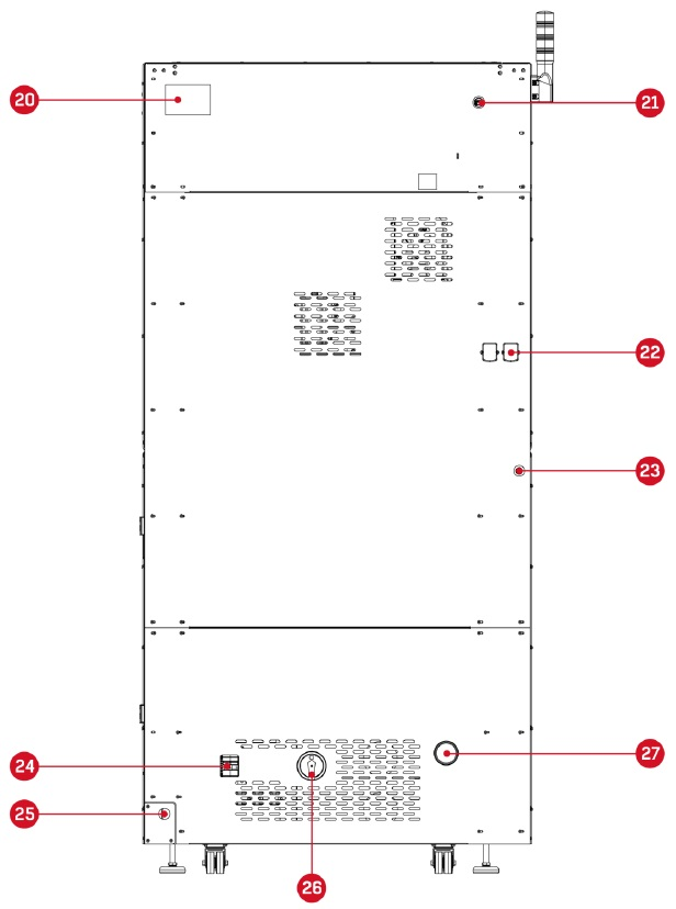
Fig. 1 3DGence INDUSTRY F420 printer – rear view: 20. Rating plate | 21. LAN/WLAN adapter socket 22. Access opening for the material feed system | 23. Compressed air system connection 24. Overcurrent protection |
25. Power cable inlet | 26. Main Switch 27. Clean air outlet from the filtration system
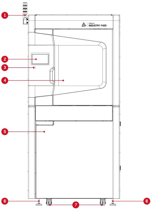
Fig. 2 3DGence INDUSTRY F420 printer – front view: 1. Light tower (optional) | 2. Display | 3. Power button
4. Working chamber door | 5. Accessories chamber door | 6. Stabilising feet | 7. Castors
Where is the latest version of the printer firmware?
Automatic firmware update
Firmware updates automatically, for this purpose “on” option in the printer menu must be set: settings → options → allow auto firmware update. If the automatic update option is enabled, the new firmware will be downloaded and automatically updated when you restart the printer. The printer must be connected to the network.
If option “allow auto firmware update” is set to “off” the firmware cannot be updated.
Manual firmware update
- Upload the attached firmware file to the pendrive.
The latest printer firmware with update instructions are available at: www.3dgence.com/support in the Firmware category (the Firmware category is available after creating the account and registering the device). - Plug the pendrive in the printer.
- Choose the firmware file from the pendrive and run the printing process.
- The print will update the firmware.
How to abort 3D printing process?
When you select the multifunction button basic information about the printed model is displayed and the printing process can be interrupted (Fig. 1). Before the “abort” button is selected a confirmation, message is displayed.
The printing is not aborted immediately – it is stopped after the last commands in the printer buffer have been executed.
NOTE: the “abort” command is irreversible – the aborted process cannot be resumed.
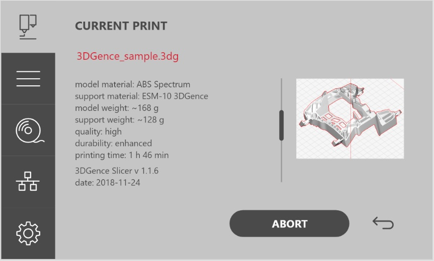
Fig. 1 Model information screen
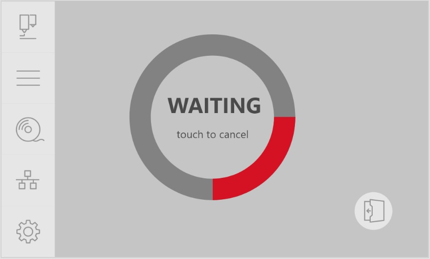
What does mean option “wait for print”?
When you select the “wait for print” option, the printer door will be locked, and you will be asked to confirm on the display that all print preparation steps have been completed. After confirmation, the screen shown in Fig. 1 will appear, the device will start preheating, after which the printer will automatically start the first job (printing), which will be sent to the device and will match what is installed in the printer. For the printing to start, this uploaded file must match the module installed in the device, the heatbed type and the type of materials loaded. In the “wait for print” mode no printer operations can be performed.
What operating status presents the light tower?Lorem ipsum
The tower is a signalling device whose task is to generate visual or visual and sound signals. A clear light or sound signal informs those who are in the vicinity about the mode. in which the machine is currently operating. This component is an optional equipment item and is primarily aimed at customers in the industrial sector. The acoustic signal indicates that there is a serious malfunction of the device that requires operator action.
Below are presented generated colours of the operating status signals with their meanings:
- continuous green – all systems are operational,
- continuous orange -a malfunction or warning that does not affect the continuity of ongoing device processes,
- continuous red – a serious malfunction or error that prevents the work process from continuing. Operator’s action required,
- intermittent orange – the device is busy, a manufacturing or preparation process is in progress.
How to activate the material from inactive material bay?
- Switch on the printer in accordance with the procedure described in FAQ: How to switch on the printer?
- Start the assistant for changing the active material bay to inactive by selecting material icons → material icons you want to change → “swap” button. Follow the messages displayed on the printer screen.
- The corresponding hotend will be set to the active position, the printer will read the axis reference positions and the print module will be set up in the cleaning station.
- A message will appear on the printer screen indicating that the unloading will start from the active bay when the hotend is heated up.
- When the correct temperature is reached, the material unloading process from the active bay will start automatically. Initially, the material will be extruded to facilitate its subsequent withdrawal from the hotend.
- When material is unloaded from the active bay, material from the inactive bay will be automatically loaded into the hotend.
- After loading material to the hotend heating will be switched off and a message will be displayed confirming the successfully completed process. When loaded, this bay will be the active one.
- Remove the material from the appropriate bay in the material chamber. Remember to store material in a dry place, protected against direct sunlight.
If one of the bays is empty and there is material preloaded into the MLS (bay inactive), the “swap” option is replaced by the “activate” option. Select the “activate” option to start the material loading assistant for the hotend from an inactive material bay. When loaded, this bay will be the active one.
How to clean the print tips?
Each time after the printing is completed, it is recommended to visually check the hotend tips for dirt. Dirty hotend tips can adversely affect the quality of printed models. That is why when they are found to be dirty it is recommended to clean the hotends from molten/burnt material that may be on the outside of the nozzle or its cover.
For this purpose:
- Switch on the printer in accordance with the procedure described in FAQ: How to switch on the printer?
- Set the heatbed in a position that allows good access to the hotends using the options: settings → maintenance → maintenance position.
- Warm up the T0 hotend using the option: settings → manual control → set temperature and use the +/- keys to set the desired temperature:
• for module M280 up to 265°C,
• for module M360 up to 320°C,
• for module M500 up to 400°C. - Warm up the T1 head with the option: settings → manual control → set temperature and use the +/- keys to set the desired temperature:
• for module M280 up to 220°C,
• for module M360 up to 265°C,
• for module M500 up to 265°C. - Set the T0 hotend in the active position with the option: settings → manual control → tool → model.
- Wear protective gloves.
- Gently remove any molten/burnt material from the T0 nozzle with non-combustible material or tweezers.
- Set the T1 head in the active position with the option: settings → manual control → tool → support.
- Gently remove any molten/burnt material from the T1 nozzle with non-combustible material or tweezers.
- After cleaning the hotends, turn off the heating with the option: settings → manual control → set temperature.
How to clean the heatbed?
A dirty or greasy printer’s heatbed can make printing difficult or completely impossible. It is recommended to clean the heatbed each time after printing is finished or before it is started. Clean the printer’s heatbed by following the instructions below.
- Switch on the printer in accordance with the procedure described in FAQ: How to switch on the printer?
- Set the heatbed in a position that makes it possible to clean it using the options: settings → maintenance → maintenance position.
- Switch off all printer heating elements using the option: settings → manual control → set temperature. Allow to cool completely and reach the ambient temperature.
- Open the work chamber door with the button on the main screen in the lower right-hand corner.
- Switch off the printer in accordance with the procedure described in FAQ: How to switch off the printer?
- Wear protective gloves.
- Clean the heatbed surface of any plastic residue with a spatula.
- Clean the bed with a damp cloth and then wipe dry with a paper towel.
- Degrease the bed with a cloth soaked in ethyl alcohol or isopropyl alcohol and wait for the alcohol to evaporate.
- Apply the adhesive on the heatbed according to the printing requirements of individual materials described on the 3DGence technical support page: https://3dgence.com/support/materialy.
How to remove the model from the heatbed after printing?Lorem ipsum
As soon as the printing process is completed, the cooling process will start automatically. A pie chart on the display shows the progress of the cooling process. Once the printer has reached a safe temperature, the display will return to the main screen and the working chamber door can be opened.
WARNING: After the printing process is completed, the working chamber door is locked and cannot be opened. When the temperature in the working chamber is lower during the cooling process the door can be opened, preceded by an appropriate message. The manufacturer does not recommend opening the door before the cooling process is completed. This option has been made available only to users with considerable experience with the printer. Before opening the door make sure that the hotend has cooled down and positioned at the X and Y axes zero position to prevent burn injuries.
Remove the print from the heatbed using the spatula delivered together with the printer. To do this, gently prize the print on its sides. Do not use sharp corners of the spatula but only its flat edge. Do not remove the print by force as it may cause damage to the heatbed. In case of problems when separating the printout from the heatbed, it is recommended that the heatbed should be heated and cooled down again. This process may be repeated, and it is recommended for printouts with a large base surface.
Always use gloves provided with the set when performing any operations connected with removing the model from the printer.
NOTE: Do not touch the heatbed surface with bare hands. Otherwise, the heatbed surface will be soiled, which there will impair adhesion of next prints. Use clean protective gloves.
What is the Smart Material Manager System (SMM)?
Smart Material Manager is a system developed by 3DGence in order to facilitate the 3D printer operation by using the system of SMM (Smart Material Manager) tags on dedicated printing materials, the subsystem measuring material consumption and appropriate software functions.
Among other things, the system makes it possible to:
• automatic read the material net weight, type and manufacturer, printer operating parameters for the material,
• monitor the amount of material remaining on the spool,
• communicating possible problems to the user, e.g. using inappropriate material for a .3dg file,
• control the quality of material flow during operation,
• detect the end of the material and automatic changeover to the material from the other bay.
The SMM consists of six key components:
- SMM tag reader, located in the material chamber at each material bay;
- SMM tag including material data, located on a spool of material from the Certified Material Database;
- Measuring system that continuously controls the amount of material fed;
- Material depletion sensor;
- Automatic material loading system.
How to unload the filament?
- Turn on the printer.
- Start the material unloading assistant by selecting material icon → material bay to be unloaded material to → “unload” button. Follow the messages displayed on the printer screen.
- The corresponding hotend will be set to the active position, the printer will read the axis reference positions and the print module will be set up in the cleaning station.
- A message will appear on the printer screen indicating that the unloading will start when the hotend is heated up.
- When the correct temperature is reached, the material unloading process will start automatically. Initially, the material will be extruded to facilitate its subsequent withdrawal from the hotend.
- After material unloading, the heating will be switched off and a message will be displayed confirming the correct unloading.
- Remove the material from the appropriate bay in the material chamber. Remember to store material in a dry place, protected against direct sunlight.
Where is the serial number of the printer?
The printer can be identified by the serial number, which can be found on the nameplate on the back side of the printer (Fig.1). You can also check the serial number on the device display.
The serial number starts with a symbol: S/N F420, which should be provided when contacting the 3DGence Technical Support.
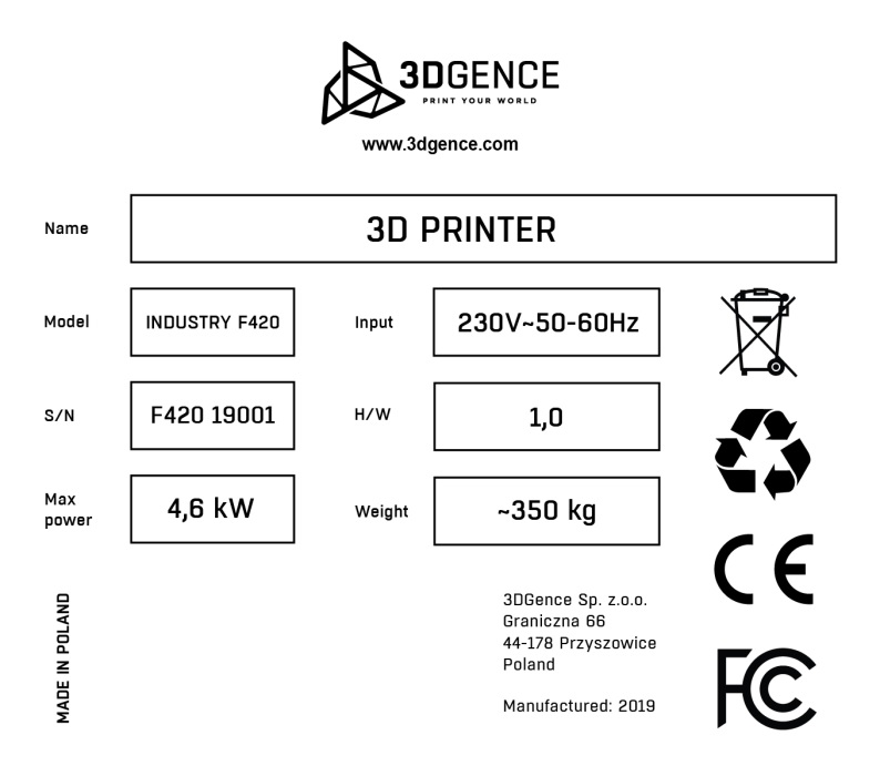
Fig. 1 Rating plate of the unit
How to load the filament?
- Turn on the printer.
- Open the filament chamber.
- Make sure that the material bay in the material chamber where you want to load the new material is empty. Also, make sure that there is no material in the material feeding system and, in the extruder, (this does not apply to the first material loading).
If material is loaded, first start the material unloading assistant by selecting: material icon → material bay to be unloaded material to → the “unload” button. - Start the material loading assistant by selecting material icon → material bay icon to be loaded material to → “load” button. Follow the messages displayed on the printer screen.
- The corresponding hotend will be set to the active position, the printer will read the axis reference positions and the print module will be set up in the cleaning station.
- Place the material in the appropriate material bay in the material chamber. Cut the end of the material at an angle of 45° and straighten the end. Slide and gently push the end of the material into the input opening of the filament feed mechanism.
- The sensor in the filament load assist module reads the presence of material and the printer starts the preloading procedure beyond the filament loading assist module.
- The printer will automatically read data from the NFC tag placed by the manufacturer on the material spool. If a spool of material with no NFC tag is loaded, a screen with the choice of material type will appear (using this option will prevent the use of the NFC system functionality).
- Then the loading of the material into the extruder will continue and at the same time the heating of the corresponding hotend will start.
- When the hotend reaches the nominal extrusion temperature for the material, the material will be automatically fed to the hotend.
- After the material is extruded from the hotend, the heating will be switched off and a message will appear confirming that the material has been properly loaded.
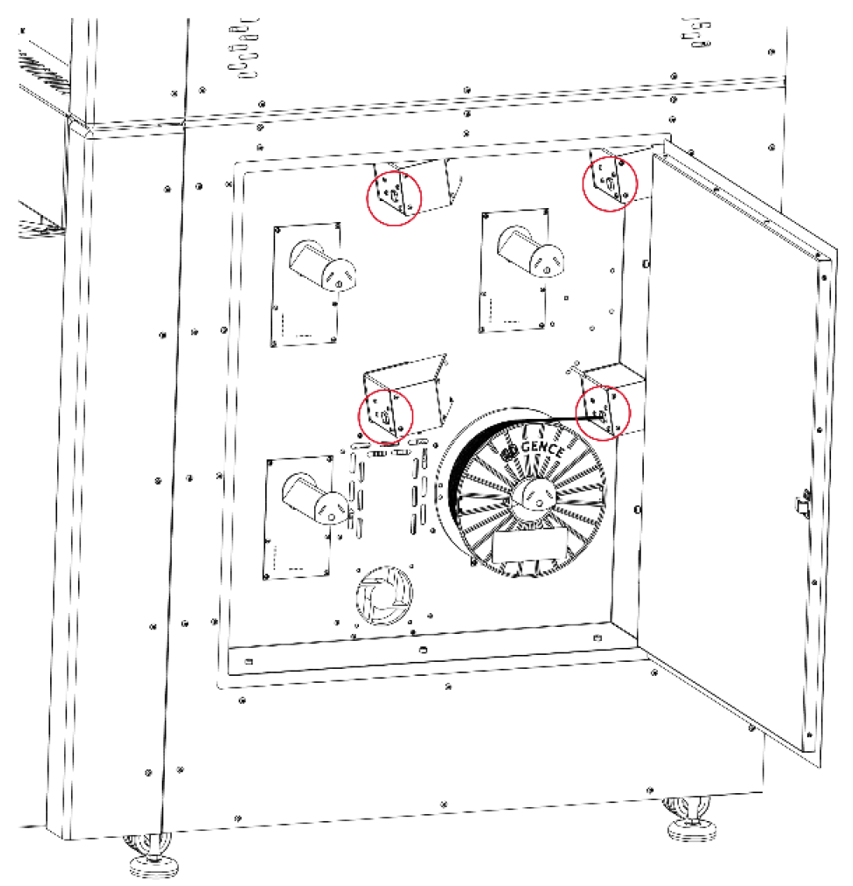
Fig. 1 Location of the entrance holes for the filament feed module
NOTE:
- Material bay 1 and material bay 2 for model material can be loaded with two the same materials (the same type and manufacturer). Otherwise, an error will appear on the printer screen stating that the materials do not match, and the loading process cannot be completed. The material will then be unloaded from the filament feed module.
- Material bay 3 and material bay 4 for support material can be loaded with two the same materials (the same type and manufacturer). Otherwise, an error will appear on the printer screen stating that the materials do not match, and the loading process cannot be completed. The material will then be unloaded from the filament feed module.